
20-175003
View detailed technical data, stock status, and sourcing information for: 20-175003
DODParts.com distributes related products varnishes dopes paints, aircraft parts and consumables, electrical parts, fittings and other components for the aerospace and defense industries. Submit the short price quote form for part 20-175003 to receive an up to date pricing and availability quote by email.

A resistor whose ohmic value cannot be adjusted or varied. The resistance element consists of high resistance wire (or ribbon) either wound on an insulated form or constructed so as to be self-supporting. The item must have inherent characteristics of inducing self-inductance. Opposition to current flow is an inherent property of the resistance wire and is manifested by the heat dissipation in the resistor. Exclut s suppressor, ignition interference. See also resistor (1), fixed, wire wound, noninductive.
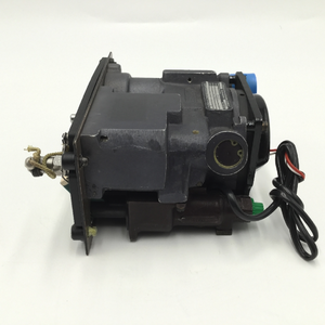
1.437 inches minimum and 1.563 inches maximum body width, 1.660 inches minimum and 1.960 inches maximum center to center distance between terminals parallel to length, +0.1177 to 0.1214 inches thread pitch diameters, 2.510 inches maximum body length, multipole-multiple actuator type body style
Product Characteristics
Below you’ll find the complete technical specifications and performance data for this part, including material details and compliance information.
- Thread Pitch Diameters
- +0.1177 to 0.1214 inches
- Body Style
- multipole-multiple actuator type
- Body Length
- 2.510 inches maximum
- Body Width
- 1.437 inches minimum and 1.563 inches maximum
- Center To Center Distance Between Terminals Parallel To Length
- 1.660 inches minimum and 1.960 inches maximum
- Center To Center Distance Between Terminals Parallel To Width
- 0.719 inches minimum and 0.781 inches maximum
- Distance Between Centerlines Of Mounting Facilities Parallel To Body Length
- 2.046 inches minimum and 2.078 inches maximum
- Distance Between Centerlines Of Mounting Facilities Parallel To Body Width
- 0.719 inches minimum and 0.781 inches maximum
- Fragility Factor
- moderately rugged
- Boss Height
- 0.109 inches minimum and 0.171 inches maximum
- Mounting Surface To Terminal End Distance
- 2.553 inches maximum
- Pole Quantity
- 2
- Arc Quenching Method
- magnetic blowout
- Mounting Facility Type And Quantity
- 4 threaded hole
- Storage Type
- general purpose warehouse
- Special Handling Feature
- magnetic
- Thread Quantity Per Inch
- 32
- Maximum Continuous Load Current Rating Per Pole
- 20.0 amperes ac all locations
- Operating Voltage Type And Rating Per Pole In Volts
- 240.0 ac all locations
- Maximum Interrupting Capacity Current Type And Rating Per Pole In Amps
- 1000.0 ac all locations
- Circuit Protection Type
- overcurrent all locations
- Trip Release Method
- magnetic all locations
- Trip Release Characteristic
- time delay all locations
- Ultimate Trip Rating Of Continuous Current Rating Per Pole In Percent
- 115.0 all locations
- Reset Method
- manual
- Main Contact Tripping Mechanism Type
- trip free
- Manual Actuator Type And Quantity
- 2 toggle
- Actuator Function
- trip-reset
- Actuator Position Designation
- at each pole
- External Actuator Linkage Arrangement
- one and two linked
- Internal Trip Release Configuration
- series trip all locations
- Nominal Thread Size
- 0.138 inches
- Trip Delay Time In Seconds Per Rated Continuous Current
- 0.130 minimum at 200 pct and 1.600 maximum at 200 pct all locations
- Inclosure Protection Type For Which Designed
- shock resistant and vibration resistant
- Frequency In Hertz
- 60.0 all locations
- Material
- plastic case
- Test Data Document
- "81349-mil-c-55629 specification (includes engineering type bulletins, brochures,etc., that reflect specification type data in specification format; excludes commercial catalogs, industry directories, and similar trade publications, reflecting general type data on certain environmental and performance requirements and test conditions that are shown as "typical", "average", "nominal", etc.)."
- Thread Series Designator
- unc
- Terminal Type And Quantity
- 4 threaded stud
- Specification/Standard Data
- 81349-mil-c-55629/3 government specification
Replaces National Stock Numbers
Below is a list of NSNs that have been officially superseded by this NSN:
| NSN | Name | Date |
|---|---|---|
| 5925-00-400-4947 | No Name Available | 03/01/1984 |
| 5925-00-927-5411 | No Name Available | 12/04/2018 |
| 5925-00-941-8030 | No Name Available | 06/01/2007 |
| 5925-00-956-8331 | No Name Available | 11/24/2003 |
| 5925-01-439-4550 | No Name Available | 12/01/1999 |
Related Parts
This NSN group includes multiple components designed to meet specific performance and operational standards. Each listing provides detailed specs, functionality data, and replacement compatibility information:
| Part Number | Name |
|---|---|
| 014246-0102 | Circuit Breaker |
| 124-0048-996 | Circuit Breaker |
| 195-220-101 | Circuit Breaker |
| 20-175003 | Circuit Breaker |
| 454-0058-029 | Circuit Breaker |
| AM2-Z19-102 | Circuit Breaker |
| AM33MG6-20-110-230VAC60C5 | Circuit Breaker |
| AM33MG6-20-125-C5 | Circuit Breaker |
| AM33MG6-20-230-60-5 | Circuit Breaker |
| AM33MG6-20-250-5-60 | Circuit Breaker |
| AM33MG6-20-250VAC60C5 | Circuit Breaker |
| AM33MG620-125-60 | Circuit Breaker |
| APL11 20AMP 60HZ.CURVE 6 | Circuit Breaker |
| M55629/3-102 | Circuit Breaker |
| SW251-2 | Circuit Breaker |
| W92X11-3-20 | Circuit Breaker |
| XAM33-20-250V5 | Circuit Breaker |
| XAM33-20-250VAC60C5 | Circuit Breaker |
FAQs
Find helpful answers about installation, operation, maintenance, compliance, and troubleshooting.
What is the FSCG of the NSN 5925-01-019-9519?
Does the NSN 5925-01-019-9519 have a Schedule B code assigned?
Does NSN 5925-01-019-9519 require demilitarization?
Does NSN 5925-01-019-9519 contain precious materials?
Does NSN 5925-01-019-9519 contain hazardous materials?
When the NSN 5925-01-019-9519 was assigned to the Federal Catalog?
Professional Distribution
Certified to meet the strict requirements of defense, aerospace, and hazardous materials distribution.
- ITAR Registered
- DDTC Registered
- HAZMAT Certified
- AS9120 Quality Standards
- 100% Quality Inspections
You May Also Like
Browse other in-demand NSN parts sourced by professionals in defense, aerospace, and manufacturing sectors. Each component meets strict standards for quality and performance.
Pricing
Submit your request below and our team will respond quickly with up-to-date pricing, delivery estimates, and stock information: